01
Where flow begins
Pump housing and impeller
The moving impeller transfers energy to the fluid. The pump housing guides the flow into the circuit; the operating point is assessed against the specific model’s technical data.

SBT / TECHNOLOGY
From fluid movement to motor and control components. Explore the structure behind circulation through genuine SBT product imagery.
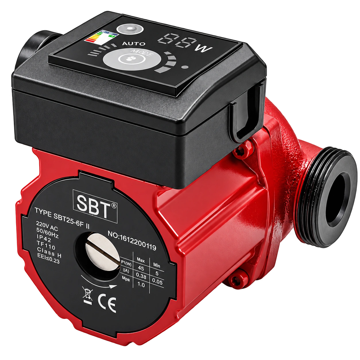 PRODUCT VIEW / SBT
SBT III / INTERNAL CONSTRUCTION
This original SBT III-series diagram shows component positions and how the assembly fits together.
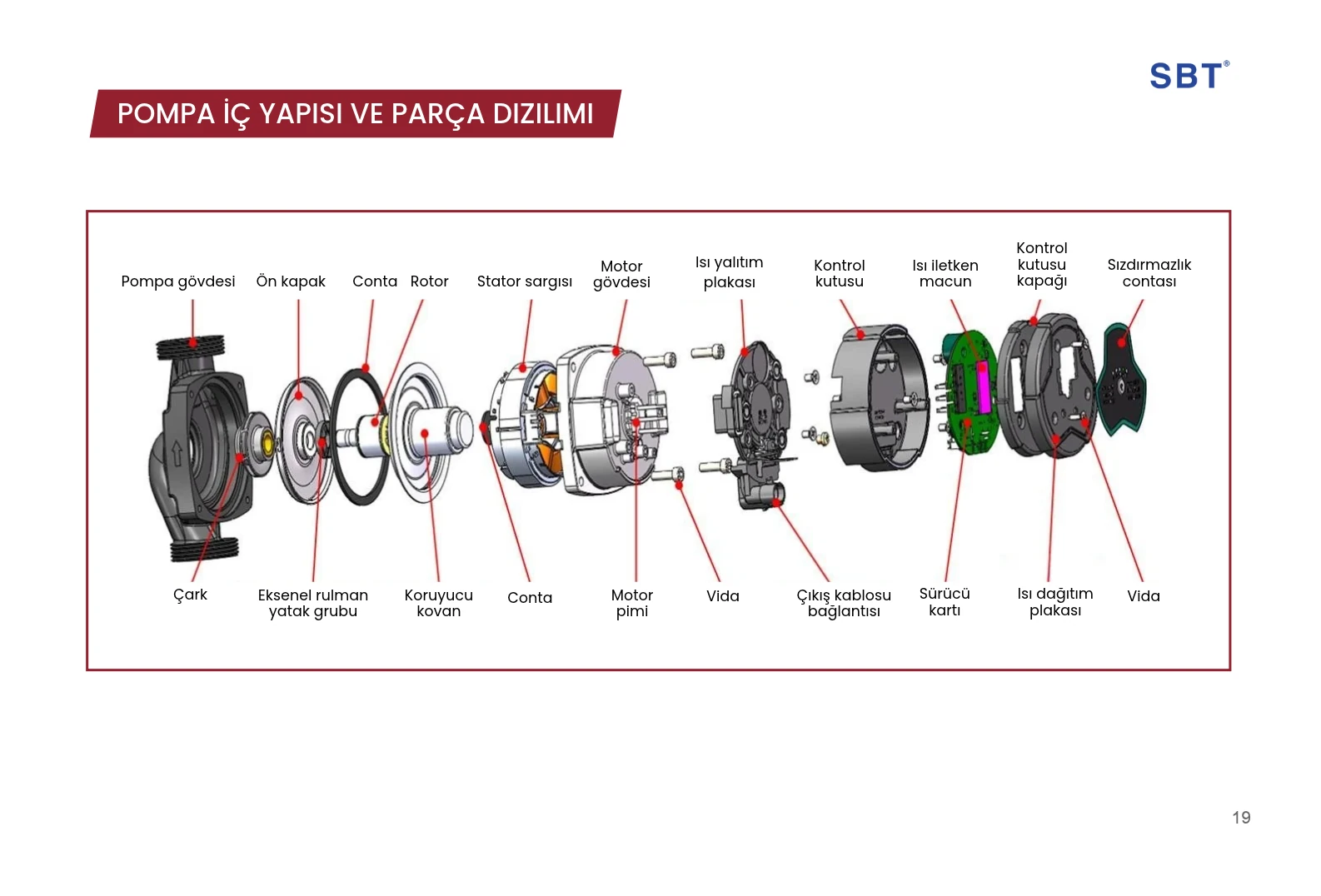
FROM COMPONENT TO ASSEMBLY
Where flow begins
The moving impeller transfers energy to the fluid. The pump housing guides the flow into the circuit; the operating point is assessed against the specific model’s technical data.
At the center of motion
The magnetic field generated by the stator winding drives the rotor. The motor housing provides structural support for these components.
The control interface
The diagram identifies the control box and driver board as separate components. Available settings and control methods depend on the model’s hardware and documentation.
The details that complete it
Gaskets support sealing at the joints. The insulation and heat dissipation plates, together with the thermally conductive compound, serve distinct roles in the thermal structure shown.
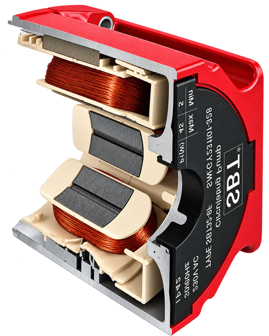
CONSTRUCTION, CONTROL AND APPLICATION
A pump interface does not mean that every product offers the same control features. Refer to the specific model’s published technical information for operating modes, settings and limits.
Energy-aware operation considers a model suited to the application and appropriate operating settings. This page does not replace a performance curve or model-specific technical data.
Explore SBT product series